
A 2000 kVA compact substation is usually bought because it removes a building from the project schedule. One factory-built enclosure arrives with the transformer, MV switchgear, LV board and internal wiring already assembled, and the site work reduces to a concrete pad, a few cable pits and a termination. That convenience hides the real risk: once the enclosure is built, its footprint, clearances and thermal behaviour are fixed, and every one of them was decided from data you supplied at enquiry stage. This guide covers what a 2000 kVA package contains, the envelope to plan for, the layouts offered, and the protection decisions that are expensive to change later.
It is written for procurement managers and electrical engineers specifying packaged substations for industrial plants, renewable projects and utility distribution. Typical ratings sit in the 11–35 kV MV range with a 400/415 V LV output, and the transformer inside is built to the same design rules as a separately mounted unit of the same rating.
What a 2000 kVA compact substation actually includes
A package substation is three functional compartments sharing one enclosure and one plinth:
- MV compartment — incoming cable termination, a load break switch or vacuum circuit breaker, protection and control, metering, and sometimes a voltage transformer for sensing.
- Transformer compartment — the transformer itself, behind a partition, ventilated through louvred doors, with the LV taken to the board through a busbar or flexible link.
- LV compartment — main incomer, outgoing feeder ways, metering, power factor correction if specified, and space for the customer’s own control equipment.
The transformer is either oil-immersed or cast resin dry-type, and that choice drives everything downstream: enclosure size, ventilation strategy, fire provisions, permitted mounting locations and the protection devices fitted. At 2000 kVA most outdoor packages still use oil for economy and overload capability, but dry-type becomes the default where the unit sits inside a building, in a high fire risk area, or under a specification that prohibits oil.
Typical dimensions and how to plan the envelope
Dimensions vary with manufacturer, transformer type, MV switchgear brand and whether a walk-in LV room is required. The figures below are budget-stage planning numbers only — use them to size the plot and check transport, then replace them with the certified outline drawing supplied after order.
| Parameter | Typical planning range at 2000 kVA | What moves the number |
|---|---|---|
| Overall length | 5.0 – 7.5 m | Walk-in LV room vs. a compact LV cubicle; separate metering panel |
| Overall width | 2.3 – 3.2 m | MV switchgear depth and whether an internal maintenance aisle is provided |
| Overall height | 2.6 – 3.2 m | Ventilation stack, roof profile and transport height limits on the route |
| Transformer compartment | about 2.0 – 2.8 m of the length | Cooling method, clearances to the partition, oil containment details |
| Operating mass | 7 – 12 t | Oil-filled vs. cast resin, enclosure gauge, plinth type |
| Pad beyond the plinth | 300 – 600 mm on operating sides | Door swing, drainage fall, cable bending radius |
Two numbers deserve attention first. Width above roughly 2.5 m usually changes the transport classification and can require a permit, and total mass sets whether you need a crane or a lorry-mounted loader. Both are site-specific, and both are far cheaper to settle during layout review than at delivery.
Layouts you are likely to be offered
Manufacturers describe these differently, but four arrangements cover most 2000 kVA projects.
Single-ended radial
One MV cable in, one transformer, one LV board. It is the standard arrangement for a plant supplied at one point and the cheapest to build. The limitation is obvious: any MV fault or planned outage takes the whole load down.
Ring with a tee-off
Two MV cable positions in a ring main unit feed the transformer tee-off. The site can be isolated and the ring restored from either direction, which suits industrial parks and utility feeders where continuity matters more than first cost.
Double transformer, sectionalised LV
Two units feed an LV board split by a bus section breaker, so either transformer can carry the essential load while the other is out. This is the layout specified when there is a defined critical load, and it roughly doubles the enclosure length and the pad.
Separate metering bay
Where the utility requires sealed metering the consumer cannot reach, the MV metering unit becomes a separate locked compartment with its own door. Ask early — retrofitting a partitioned metering bay into a finished enclosure is not practical.
MV and LV compartments
MV side
At this rating the incoming device is normally a vacuum circuit breaker if you need automatic tripping, or a load break switch with fuses if the upstream network provides fault clearance and you mainly need local isolation. The distinction belongs in the enquiry: it determines who can operate the device and what the utility will accept at the interface. Whatever is fitted, insist on a visible and lockable earthing position, cable test access without removing terminations, and an interlock between the earthing switch and the compartment door.
LV side
The LV board is where most late changes happen, because feeder schedules are rarely final when the order is placed. Decide three things up front: the number of usable outgoing ways including spares, the form of separation required, and whether power factor correction, generator changeover or surge protection belongs inside the enclosure. Adding ways later usually means a second cubicle and a longer enclosure.
Protection, grading and interlocks
A compact substation concentrates MV protection, LV protection and mechanical safety devices in one box, and the settings must be graded across both. The table below lists the functions worth confirming on the drawing rather than assuming.
| Function | Device / ANSI reference | Located in | Setting and verification |
|---|---|---|---|
| Phase overcurrent and earth fault | 50/51, 50N/51N | MV protection relay | From the network coordination study; verified by injection testing |
| Unit protection for the transformer | 87T differential | MV relay, CTs on both windings | Specified where the rating and network make it worthwhile |
| Restricted earth fault | 64REF via neutral CT | Transformer neutral | Confirm the CT is fitted before the tank is closed |
| Thermal and overload monitoring | 49, winding and oil temperature contacts | Transformer and LV incomer | Alarm and trip contacts wired as specified, not left unconnected |
| Oil-immersed mechanical protection | Buchholz relay / sudden pressure device | Transformer compartment | Trip or alarm function decided per the plant philosophy |
| Surge protection | Metal-oxide surge arresters | MV line entrance | Rating aligned to the system insulation level |
| LV incomer and feeders | Air circuit breaker / MCCB with electronic trip | LV compartment | Selectivity graded against the upstream MV protection |
| Mechanical interlocks | Key and bolt interlocks | MV gear, doors, LV board | Door cannot open unless the device is isolated and earthed |
| Earthing | Common MV/LV earth bar to the site grid | Enclosure earth bar | Conductor sizes per the site earthing design |
Site, foundation and cable entry
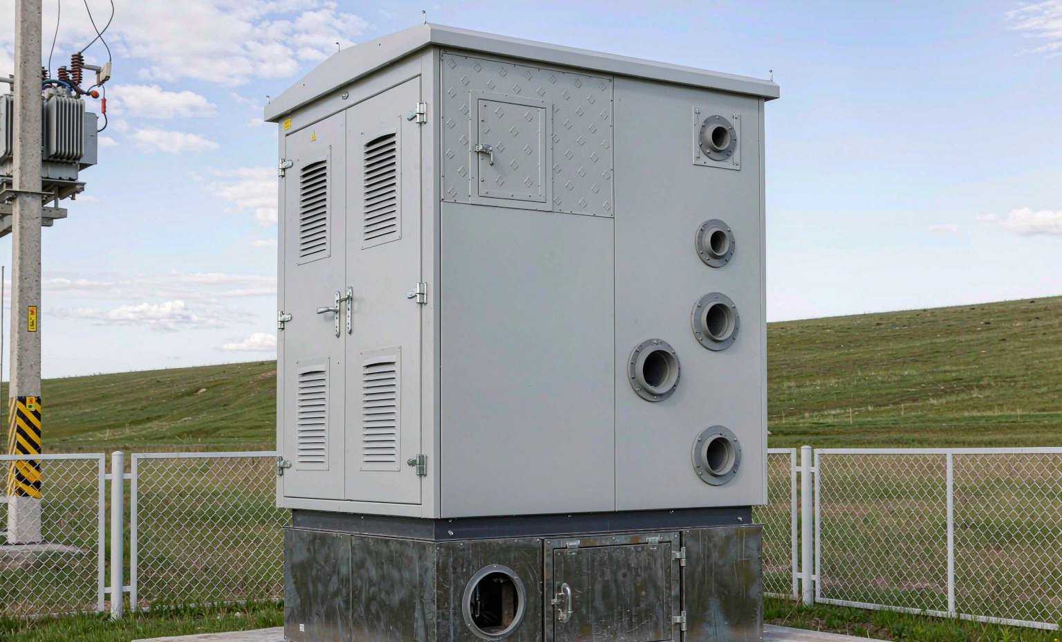
The enclosure needs a level reinforced pad able to carry the operating mass with the specified margin, normally detailed by the manufacturer as a drawing. Provide a fall for drainage, seal every cable entry against water and rodents, and keep the louvred faces clear — natural ventilation fails quickly when a wall or a stack of pallets sits 400 mm from the louvres. Cable pits should be sized for the bending radius of the finished MV cables rather than the conductor alone; the most common site delay is a pit too small to form the cables, which means breaking concrete around a finished pad. For oil-filled units above the small-volume threshold in the local rules, plan oil containment to the applicable requirement — that is a permitting question, not a manufacturer preference.
Standards and what to fix before you enquire
The specification should name the standards and state that the package must comply with them. The usual set includes IEC 62271-202 for prefabricated substations including internal arc classification, the IEC 60076 series for the transformer, IEC 62271-200 for the MV assembly, the IEC 61439 series for the LV board, and IEC 60529 for the IP rating of each compartment. Where the project follows North American practice, IEEE C37 standards may replace parts of the set; either is acceptable if stated once and applied consistently, since mixed requirements are the source of most approval delays.
Put these items in the enquiry document — each one answered now saves a drawing revision later:
- MV system voltage, insulation level and short-time withstand requirement
- Transformer rating, vector group, tapping range, cooling method, oil or cast resin
- LV voltage, frequency, neutral arrangement and earthing philosophy
- Incoming device type: load break switch, fused switch or circuit breaker
- Number of outgoing LV ways including spares, and future extension space
- Enclosure material, coating system, IP rating and corrosion class
- Ambient temperature range and installation altitude
- Internal arc classification and accessibility class required
- Metering requirements, including whether the utility needs a sealed separate bay
- Cable entry direction and sizes, transport limits, and the FAT programme
FAQ
How much space does a 2000 kVA compact substation need?
Plan for an enclosure roughly 5.0 to 7.5 m long and 2.3 to 3.2 m wide, plus operating clearance in front of the doors and cable entry space below. Treat these as budget figures and replace them with the certified outline drawing before the pad is poured.
Oil-immersed or cast resin at 2000 kVA?
Oil generally gives better overload behaviour and lower first cost outdoors. Cast resin dry-type is preferred where the unit goes indoors, where fire risk is elevated, or where oil containment cannot be provided. Local fire and environmental rules often decide it.
Is internal arc classification worth specifying?
Yes, when personnel may work near the enclosure while it is energised. The requirement changes door construction, pressure relief paths and labelling, none of which can be retrofitted economically.
Can the MV switchgear be extended later?
Only if you specify extensible switchgear and reserve enclosure length at the outset. Compact ring units are typically not extensible, so decide at enquiry stage whether future MV ways are needed.
What usually delays a compact substation project?
Incomplete feeder schedules, unresolved utility metering requirements, and site drawings issued after civil work has started. Transport permits for an over-width enclosure are the other frequent cause.
Specify the layout before you build the pad
A packaged unit rewards early decisions and punishes late ones. If you are planning a 2000 kVA installation now, send the enquiry data above and our team will review it against what we build and test. Review the compact substation range, look at the European-type compact substation layout, browse the full product catalogue, or request a quote with your single-line diagram. You can also reach us at info@xsdfftransformer.com or WhatsApp +85254162620.