
PD testing during FAT is the one acceptance test that tells you whether the insulation system you are buying is sound before it leaves the factory. It is also the test most buyers witness without really knowing what to look at. This guide explains the method defined in IEC 60270 and IEC 60076-3, the measurement circuit you should see on the test floor, the sequence a competent manufacturer follows, and a witness checklist you can print and take with you.
It is written for procurement managers and electrical engineers who attend factory acceptance tests for 35–110 kV power transformers. If you need the broader FAT scope, start with our factory acceptance test witness checklist.
Why partial discharge testing belongs in your FAT
Partial discharge (PD) is a localised electrical discharge that only partially bridges the insulation between conductors. It does not cause immediate breakdown, but it erodes insulation over time and is one of the leading causes of in-service transformer failure. Sources include voids in solid insulation, free particles in oil, protruding electrodes, floating potentials and poor bonding of core and clamping structures.
The reason PD measurement belongs at FAT rather than on site is simple: the factory has a controlled electromagnetic environment, a calibrated high-voltage supply, and the tooling to correct a problem while the unit is still on the shop floor. Once a transformer is energised at site, a PD source becomes a warranty argument rather than a fixable defect.
Standards that define the method
Three documents govern how PD is measured and how results are judged. Your purchase specification should name them explicitly:
- IEC 60270 — High-voltage test techniques, partial discharge measurements. Defines the measuring circuit, calibration procedure, bandwidth and the quantity actually reported (apparent charge).
- IEC 60076-3 — Power transformers: insulation levels, dielectric tests and external clearances in air. Specifies when PD measurement is performed during dielectric tests and the associated test voltages.
- IEEE C57.113 — Guide for partial discharge measurement in liquid-filled power transformers and shunt reactors. Widely referenced in North American and IEC-aligned project specifications.
For a full comparison of what these standards require across routine, type and special tests, see our power transformer testing standards guide.
How the measurement circuit is set up
Before the test starts, walk the test bay and confirm the following items are in place. A missing item here is the most common cause of a disputed result.
| Item | What to verify |
|---|---|
| Coupling capacitors | Rated for the test voltage, PD-free at the measurement level, connected to the terminals under test |
| Measuring impedance | Matched to the coupling capacitor and the instrument, bonded to a clean earth point |
| PD instrument | Calibration certificate in date; calibration pulse injected at the terminals before and after the test |
| Earth system | Single, low-impedance test earth; temporary earth leads must not form loops around the tank |
| Tank and core bonding | Confirmed to the manufacturer’s drawing; floating metal parts are a classic false source |
| Bushings and test leads | Clean, dry, correctly screened; corona rings fitted where specified |
| Oil condition | Treated and settled; entrained bubbles after oil filling produce spurious readings |
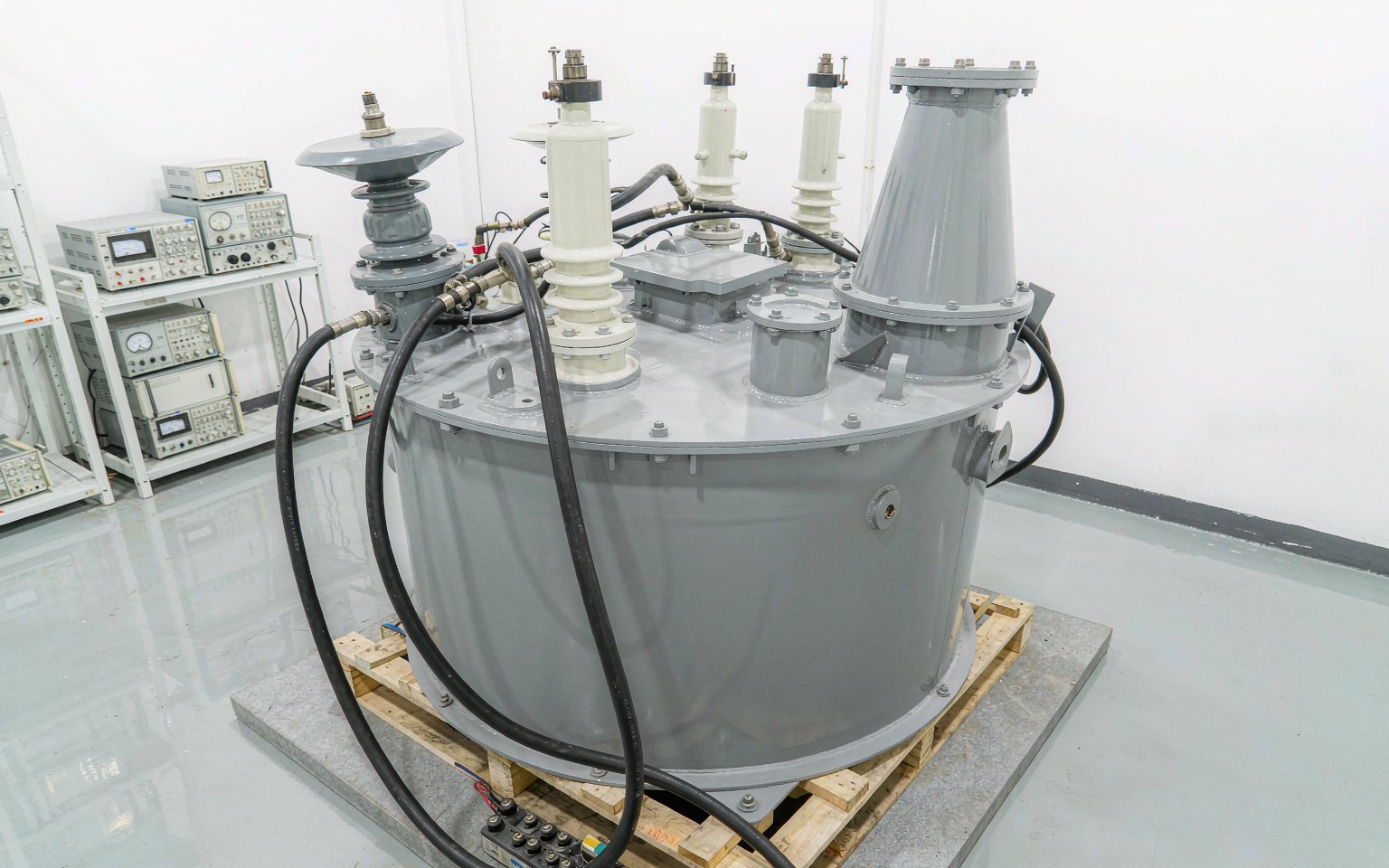
Step-by-step: the PD test sequence during FAT
The exact sequence depends on the insulation levels in your specification, but a competent test follows the same logic every time:
1. Calibration
A known charge is injected into the measurement circuit at the terminal being tested. This converts the instrument reading into a calibrated quantity and proves the coupling path works. Ask to see the calibration trace before and after the voltage test — not only before.
2. Background measurement
With the transformer de-energised, the background interference level is recorded. If the background is a significant fraction of the limit in your specification, the test result will be meaningless. External sources to eliminate include crane motors, welders, radio transmitters and unsuppressed lighting in the test bay.
3. Voltage application
Voltage is raised in defined steps and held for the specified durations. In the long-duration induced voltage test with PD measurement, the unit is energised at an enhanced voltage and frequency, and PD is recorded continuously rather than spot-checked.
4. Measurement and recording
The instrument records magnitude, phase position and repetition rate over the hold period. A rising trend during a hold is more significant than a single momentary reading. Insist on a printed trace with time stamps, not just a pass/fail statement.
5. De-energising and repeat calibration
Calibration is repeated at the end. If the calibration constant has drifted, the session is invalid. This is the step that is most often skipped when a test is running late.
Reading the result: what acceptance really means
Acceptance criteria are set in the purchase specification, not by the test laboratory. IEC 60076-3 defines the test method and the associated voltage levels; the permissible discharge magnitude, the trend behaviour allowed during holds, and what happens on a first exceedance are commercial and technical decisions that belong in your technical schedule.
When you write the specification, settle three things before FAT: the acceptance magnitude, whether a rising trend is grounds for rejection, and the procedure if the limit is exceeded once (re-test after rest, or investigation and repair). Deciding these on the test floor is how disputes start.
Buyer’s witness checklist
| # | Check | Pass condition |
|---|---|---|
| 1 | Test procedure available | Written procedure references IEC 60270 and IEC 60076-3 and matches the approved drawing set |
| 2 | Instrument calibration | Certificate in date, serial number matches the instrument on the floor |
| 3 | Calibration pulse injected | Performed before and after the voltage test, trace attached to the report |
| 4 | Background level recorded | Recorded with the unit de-energised and noted in the report |
| 5 | Earth and bonding | Single test earth; tank, core and clamping structures bonded per drawing |
| 6 | Coupling capacitors | PD-free at test voltage; correct rating and position |
| 7 | Oil condition and settling time | Treatment records available; settling period observed after filling |
| 8 | Bushing condition | Clean and dry; corona control fitted where specified |
| 9 | Voltage steps and hold times | Match the specification; no skipped or shortened holds |
| 10 | Continuous recording | Full trace over each hold, with time stamps and phase information |
| 11 | External interference excluded | Non-essential equipment in the bay switched off for the duration |
| 12 | Report content | Limits applied, measured values, traces, instrument identity, signatures, date |
Common problems that cause a false fail
- External corona from the test circuit — sharp edges on temporary connections, unshielded leads or a missing corona ring show up as discharge from the transformer.
- Floating metal parts — an unconnected earthing strap or a loose clamp produces a strong, unstable signal that disappears once bonded.
- Freshly filled oil — entrained bubbles after oil filling generate readings that settle with time. Settling periods exist for this reason.
- Poor earth topology — multiple earth paths create loops that pick up noise; the fix is a single test earth.
- Industrial activity in the bay — cranes, welders and variable-speed drives are the usual culprits behind a rising background.
FAQ
Is PD testing part of routine tests or a special test?
PD measurement is specified in IEC 60076-3 as part of the dielectric test sequence for transformers where it is required; whether it is a routine or special test depends on the rating and the purchase specification. Confirm it in writing before the manufacturing programme starts.
Can PD testing damage a healthy transformer?
The test is non-destructive when performed to the specified voltage levels and durations. The risk comes from deviations — over-voltage, skipped calibration, or testing before oil has settled.
What should I do if the first measurement exceeds the limit?
Follow the procedure in your specification. In practice the first step is to rule out external sources, repeat the background check, and re-test after the specified settling period before any investigation of the transformer itself.
Does a clean FAT guarantee no PD in service?
No test guarantees future condition. A clean FAT result, with full traces and a signed report, establishes the insulation condition at dispatch and gives you a baseline for later comparison.
Who should attend the test?
Someone with authority to accept the result, ideally supported by the engineer who wrote the specification. If nobody from your side can attend, agree in advance on video witnessing and the exact documents to be provided.
Plan the PD test before you place the order
The cheapest moment to define acceptance criteria is when you write the enquiry, not at the test bay. If you are specifying a unit now, our team can review your technical schedule and confirm what the test programme will cover for the voltage class you need. See the high voltage transformer range, read more about our work as a high voltage transformer manufacturer and supplier, or request a quote with your specification.