
The vector group is the line on a transformer nameplate that causes some of the most expensive mistakes. Specify it wrongly and two transformers cannot run in parallel, earth-fault protection mis-operates, and triplen harmonics have nowhere to go.
This guide explains what a vector group is, how to decode the label, what the common groups are used for, and how to choose the transformer vector group before you issue an RFQ.
What is a transformer vector group?
A vector group is a compact code, defined in IEC 60076-1, that describes two things about a three-phase transformer:
- How the windings are connected, whether star, delta or zigzag, on both the high-voltage (HV) and low-voltage (LV) sides.
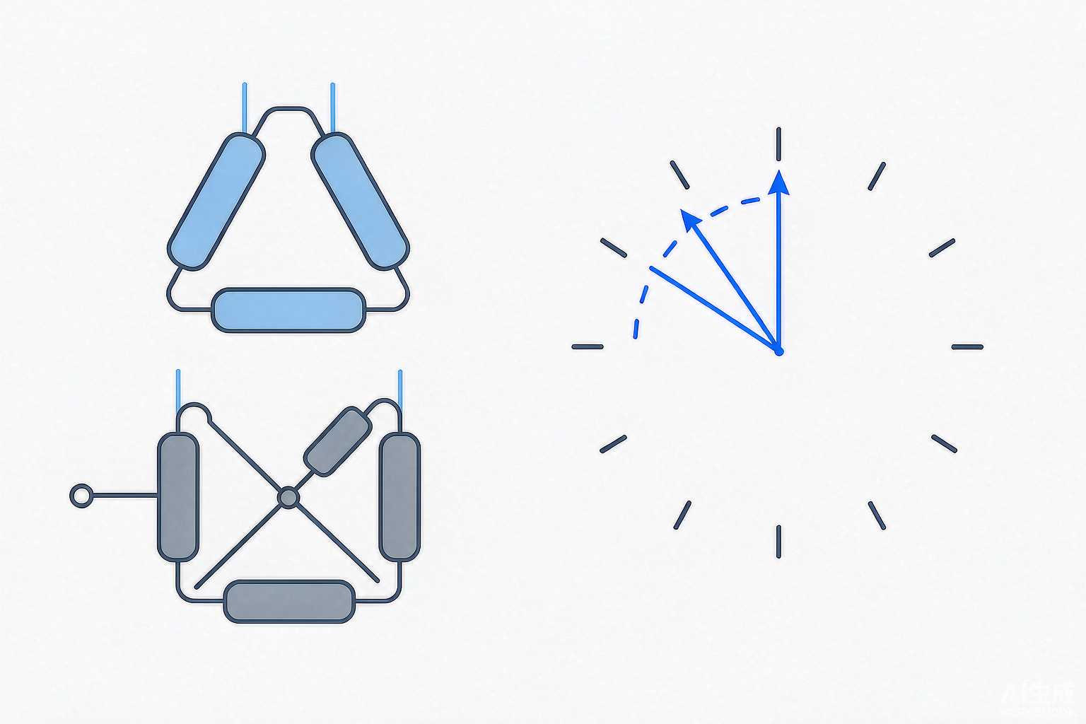
- The phase displacement between the HV and LV line voltages, expressed as a clock-hour number where each hour equals 30°.
The second part matters because a transformer does not simply scale voltage, it also shifts phase. Two transformers with identical ratings but different vector groups are not interchangeable, even if every other line on the nameplate matches.
How to read the vector group code
Take Dyn11 as the example, read left to right:
| Symbol | Meaning |
|---|---|
| D | HV winding connected in delta (uppercase = HV side) |
| y | LV winding connected in star (lowercase = LV side) |
| n | The LV star point (neutral) is brought out to a terminal |
| 11 | Phase displacement = 11 × 30° = 330°, i.e. the LV line voltage leads the HV line voltage by 30° |
So Dyn11 reads: delta-connected HV, star-connected LV with an accessible neutral, and a 30° phase lead on the LV side. Once you know the decoding rule, the Dyn11 transformer meaning follows directly from the label.
A few more, decoded:
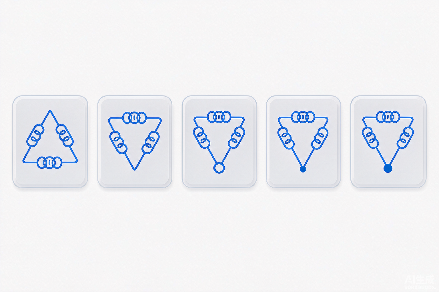
- YNd11: HV star with neutral brought out, LV delta, LV leads by 30°.
- Yyn0: star/star, both neutrals available, zero phase displacement.
- Dyn5: delta HV, star LV with neutral, 150° displacement.
- Yd11: star HV, delta LV, 30° displacement.
- YNyn0d: three-winding unit with star HV and LV neutrals plus a delta tertiary.
Clock notation in practice
Picture a clock face. Fix the HV line-voltage phasor at 12 o’clock. The number in the vector group tells you where the LV phasor points, with each hour representing 30° of displacement read in the standard anticlockwise phasor convention.
- 0 means LV and HV are in phase, with no shift.
- 11 puts the LV at the 11 o’clock position, a 30° lead relative to HV.
- 5 puts it opposite-plus-one hour, a 150° shift.
Only certain hour numbers are physically realisable for a given pair of winding connections, which is why you see 0, 5, 6 and 11 far more often than any other value.
Common vector groups and where they are used
| Vector group | HV / LV | Typical application | Why it is chosen |
|---|---|---|---|
| Dyn11 | Delta / star + neutral | The workhorse for distribution and 35 kV substation transformers | LV neutral available for earthing and single-phase loads; the delta HV blocks zero-sequence current from the upstream network |
| YNd11 | Star + neutral / delta | HV step-down in transmission and primary substations (e.g. 110/33 kV, 110/11 kV) | HV neutral can be solidly earthed as the network requires; the delta LV gives triplen harmonics a circulating path |
| Yyn0 | Star / star + neutral | Small distribution units where a neutral is needed on both sides | Simple and economical, but limited earth-fault capability and sensitive to unbalanced loading |
| Yd11 | Star / delta | Generator step-up and industrial drive supplies | Delta LV isolates the load from HV earth faults |
| Dyn5 | Delta / star + neutral | Replacement units matching legacy plant | Chosen to reproduce an existing displacement so the unit can parallel with what is already installed |
| YNyn0d | Star / star + tertiary delta | Large transmission autotransformers | Tertiary delta stabilises the neutral and absorbs harmonics |
Why the vector group matters in practice
Two transformers can only be paralleled safely if they share the same vector group, the same ratio, compatible impedance and correct polarity. A 30° displacement mismatch creates a circulating current that can exceed rated current even with no load connected, which is destructive and entirely avoidable.
Earthing depends on it too. Only a star winding with its neutral brought out gives you an earthing point, and a delta winding provides none. That determines whether you can solidly earth the system, resistively earth it, or have to add a separate earthing transformer.
Harmonics behave the same way. Triplen harmonics (3rd, 9th, 15th and so on) do not cancel in a star winding unless there is a path for them. A delta winding, on either side or as a tertiary, gives those currents somewhere to circulate instead of distorting the supply voltage.
Protection settings follow from the group as well. Differential protection has to compensate for the transformer’s phase displacement, and the current-transformer connections depend on the vector group. A relay scheme set up for Dyn11 will mis-operate on a YNd11 unit unless it is reconfigured.
Zero-sequence behaviour is the last piece: a delta winding blocks zero-sequence current from passing through. That can be what you want, or what breaks your earth-fault scheme.
How to choose the right transformer vector group
Work through these in order:
- Match the existing network first. If the transformer will parallel with or replace an existing unit, the vector group has to match, and this constraint outranks everything else.
- Does the HV side need an earthed neutral? High-voltage transmission networks commonly specify a solidly earthed HV neutral, and that calls for YN.
- Does the LV side need a neutral? If the LV feeds single-phase loads or requires an earthing point, you need yn, meaning star with the neutral brought out.
- Do you need to block zero-sequence current or absorb harmonics? Include a delta, either as a main winding or as a tertiary.
- Is the load unbalanced? If so, avoid Yyn0, whose star-star configuration handles unbalance poorly. Dyn11 is the standard remedy.
- Check your protection scheme, and confirm the relay and CT arrangements support the intended displacement.
- Follow the utility’s standard where one exists. A published network practice usually overrides preference, and Dyn11 for distribution with YNd11 for HV step-down is a very common pattern.
How the vector group is verified
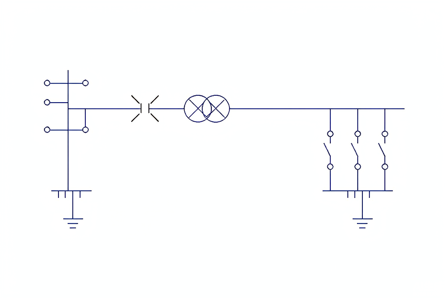
The vector group test of transformer windings confirms both the winding connections and the phase displacement. It is a routine test under IEC 60076-1, carried out on every unit before shipment rather than only on type-tested designs. The standard approaches include:
- Applying a three-phase voltage and measuring the relationships between corresponding HV and LV terminals.
- Bridge or polarity comparison methods that confirm both the winding connections and the phase displacement.
- A physical check of the nameplate against the wiring arrangement.
The result is recorded on the nameplate and in the test report. Before accepting delivery, confirm that the nameplate group matches your specification and the test report, and that your protection settings match the group you received. See our power transformer testing standards guide for where this sits in the wider test programme.
Common mistakes in transformer RFQs
- Copying “Dyn11” out of habit without checking whether the network needs an earthed HV neutral, which needs YN rather than D.
- Specifying Yyn0 where the load is significantly unbalanced, the classic cause of a drifting neutral and overheating.
- Forgetting to state the neutral requirement, including whether the neutral must be brought out and its current rating.
- Ordering a second transformer for parallel operation without matching the vector group of the first.
- Overlooking the tertiary winding where harmonic absorption or neutral stabilisation is needed.
- Not telling the supplier the protection arrangement, which leaves the CT configuration to guesswork.
Conclusion
The vector group condenses three decisions into a few characters: how each winding is connected, whether a neutral is available, and how far the LV is displaced from the HV. It governs whether transformers can parallel, how the system is earthed, where harmonics go, and how protection must be set.
We manufacture 35 kV to 110 kV power transformers to the vector group your network requires, including Dyn11, YNd11, Yyn0, Dyn5 and three-winding arrangements with a delta tertiary. Every unit is routine-tested, with the vector group verified and recorded before shipment.
Send us your single-line diagram, voltage ratio and whether the new unit must parallel with existing plant. Our engineering team will confirm the correct vector group and quote to that specification.