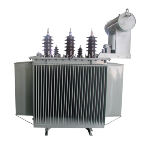
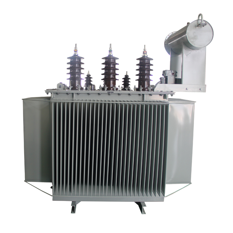
Technical Parameters & Ratings
IEC / ANSI CertifiedFactory Standard
| Rated Capacity | 630 kVA |
|---|---|
| Primary Voltage (U1) | 11,000 V (11 kV) |
| Secondary Voltage (U2) | 415 V / 240 V (3-Phase 4-Wire) |
| Vector Group | Dyn11 |
| Rated Frequency | 50 Hz |
| Cooling Method | ONAN (Oil Natural Air Natural) |
| Primary Current (I1) | 11.02 A |
| Secondary Current (I2) | 876.5 A |
| Guaranteed No-Load Loss (P0) | 810 W |
| Guaranteed Load Loss (Pk at 75°C) | 5500 W |
| Short-Circuit Impedance (Uk) | 4.5% |
| HV Insulation Level | LI 75 / AC 35 (11kV Class) |
| Temperature Rise Limits | Top Oil ≤ 50K, Winding ≤ 55K (45°C Ambient) |
| Creepage Distance | ≥ 31 mm/kV (Outdoor Tropicalized Porcelain) |
| Core & Coil Weight | 1150 kg |
| Insulating Oil Weight | 710 kg |
| Total Assembled Weight | 2250 kg |
| Overall Footprint (L×W×H) | 1500 mm × 980 mm × 1620 mm |
| Governing Standards | IEC 60076, BS 171, SON NIS, NERC Code |
Technical Highlights
- This product combines dependable transformer platform design, flexible project configuration, and practical export-oriented construction. It is suitable for applications requiring stable electrical performance, configurable voltage ratios, outdoor durability, and documentation support for international project supply.
Application Scenarios
- Utility distribution networks
- Industrial plants and workshops
- Commercial buildings and mixed-use developments
- Public infrastructure projects
- Regional and municipal power distribution systems
Key Features
- 630 kVA rated capacity with optimized core design for energy-saving applications
- Three-phase oil-immersed structure for stable outdoor operating performance
- class configuration suitable for distribution and industrial feeder networks
- Low-loss design approach intended to reduce operating cost over service life
- Supports project-based winding, voltage ratio, and accessory customization
- Suitable for utility and industrial buyers prioritizing efficiency and life-cycle value
Optional Configurations
- Low-voltage side rating and voltage ratio
- Frequency: 50 Hz or 60 Hz
- Vector group and tapping range
- Copper or aluminum winding
- Cooling method, accessory package, and monitoring option
- Tank structure, coating system, and special environmental adaptation
- Color, nameplate language, and document package
- Ambient temperature, altitude, and installation condition adaptation