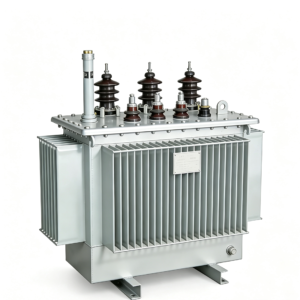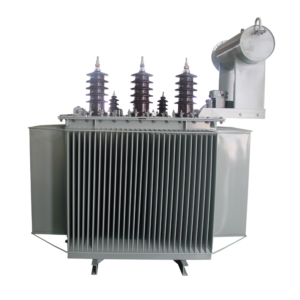
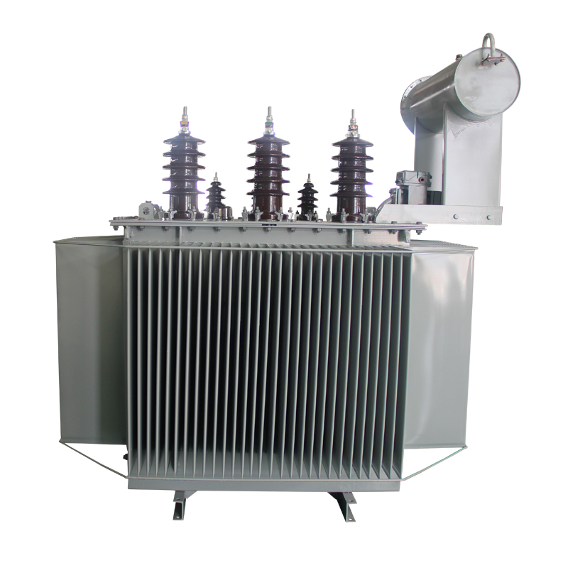
Technical Parameters & Ratings
| Rated Capacity | 2500 kVA |
|---|---|
| Primary Voltage (U1) | 11,000 V (11 kV) |
| Secondary Voltage (U2) | 415 V / 240 V (3-Phase 4-Wire) |
| Vector Group | Dyn11 |
| Rated Frequency | 50 Hz |
| Cooling Method | ONAN (Oil Natural Air Natural) |
| Primary Current (I1) | 43.74 A |
| Secondary Current (I2) | 3478.0 A |
| Guaranteed No-Load Loss (P0) | 2300 W |
| Guaranteed Load Loss (Pk at 75°C) | 17500 W |
| Short-Circuit Impedance (Uk) | 5.0% |
| HV Insulation Level | LI 75 / AC 35 (11kV Class) |
| Temperature Rise Limits | Top Oil ≤ 50K, Winding ≤ 55K (45°C Ambient) |
| Creepage Distance | ≥ 31 mm/kV (Outdoor Tropicalized Porcelain) |
| Core & Coil Weight | 3600 kg |
| Insulating Oil Weight | 2100 kg |
| Total Assembled Weight | 7200 kg |
| Overall Footprint (L×W×H) | 2100 mm × 1350 mm × 2200 mm |
| Governing Standards | IEC 60076, BS 171, SON NIS, NERC Code |
Technical Highlights
- This product combines dependable transformer platform design, flexible project configuration, and practical export-oriented construction. It is suitable for applications requiring stable electrical performance, configurable voltage ratios, outdoor durability, and documentation support for international project supply.
Application Scenarios
- Utility distribution networks
- Industrial plants and workshops
- Commercial buildings and mixed-use developments
- Public infrastructure projects
- Regional and municipal power distribution systems
Key Features
- Designed for electrical control, automation, and load-side switching functions
- Configurable internal component arrangement according to process and feeder requirements
- Supports communication, metering, and interface options for smart plant integration
- Cabinet construction suitable for industrial and infrastructure environments
- Project-oriented documentation, labeling, and wiring scheme support available
- Suitable for export supply and customized control-package delivery
Optional Configurations
- Low-voltage side rating and voltage ratio
- Frequency: 50 Hz or 60 Hz
- Vector group and tapping range
- Copper or aluminum winding
- Cooling method, accessory package, and monitoring option
- Tank structure, coating system, and special environmental adaptation
- Color, nameplate language, and document package
- Ambient temperature, altitude, and installation condition adaptation
Frequently Asked Questions
What is the advantage of an OLTC over an off-circuit tap changer?
An on-load tap changer regulates voltage while the transformer remains energized, so voltage can be corrected without interrupting supply — essential for grids with fluctuating load or renewable infeed.
How many tap positions are normally provided?
Typical OLTC ranges are +/-8 x 1.25% or +/-9 steps, with the exact range set by your voltage regulation requirement and confirmed during design review.
Which tap changer brands are used?
OLTC units are supplied with proven on-load tap changers from established manufacturers. The final brand is agreed at order stage and stated on the nameplate and test reports.
Does the OLTC require periodic maintenance?
Yes. Diverter switch oil and contacts require periodic inspection per the tap changer manufacturer’s schedule; a maintenance recommendation is included in the document package.
Can this OLTC transformer be supplied as a mobile or pad-mounted unit?
It can be configured for station, pad-mounted or containerized layouts on request, subject to the cooling and tap changer access requirements of the final design.