
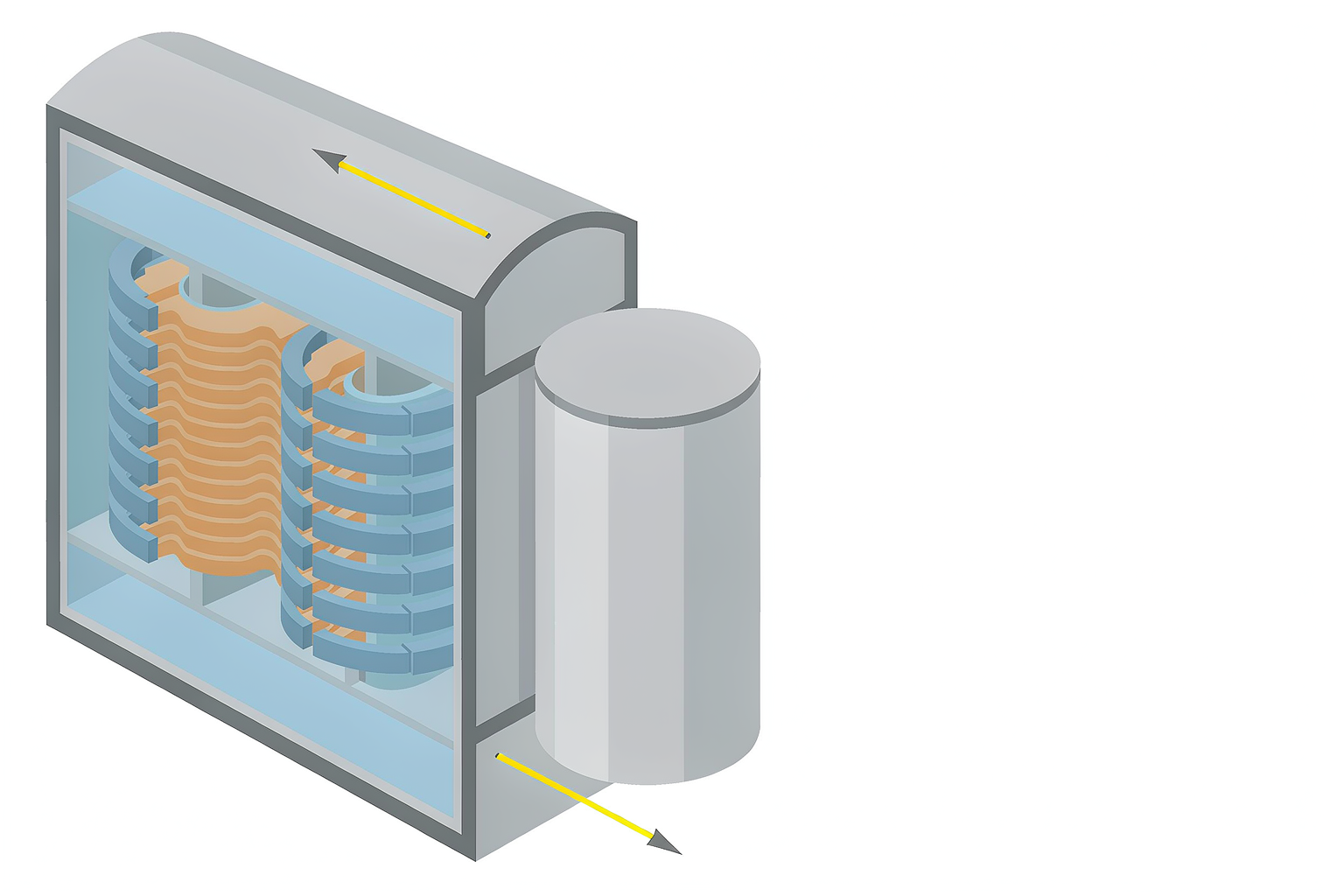
Two numbers on a transformer’s test report decide how much that unit will cost you over the next thirty years: no-load loss and load loss. For a 35 kV or 110 kV transformer that stays energised around the clock, the electricity consumed by those losses routinely adds up to more than the purchase price of the transformer itself.
This guide explains what each loss is, how the two differ, how they are measured under IEC 60076-1, and how to convert them into a single power transformer total cost of ownership figure so you can compare suppliers on equal terms.
What are power transformer losses?
No transformer is perfectly efficient. Some of the energy passing through it becomes heat and never reaches the load. That lost energy splits into two parts that behave in very different ways:
- No-load loss (iron loss or core loss), dissipated in the magnetic core.
- Load loss (copper loss or winding loss), dissipated in the windings and nearby structural parts.
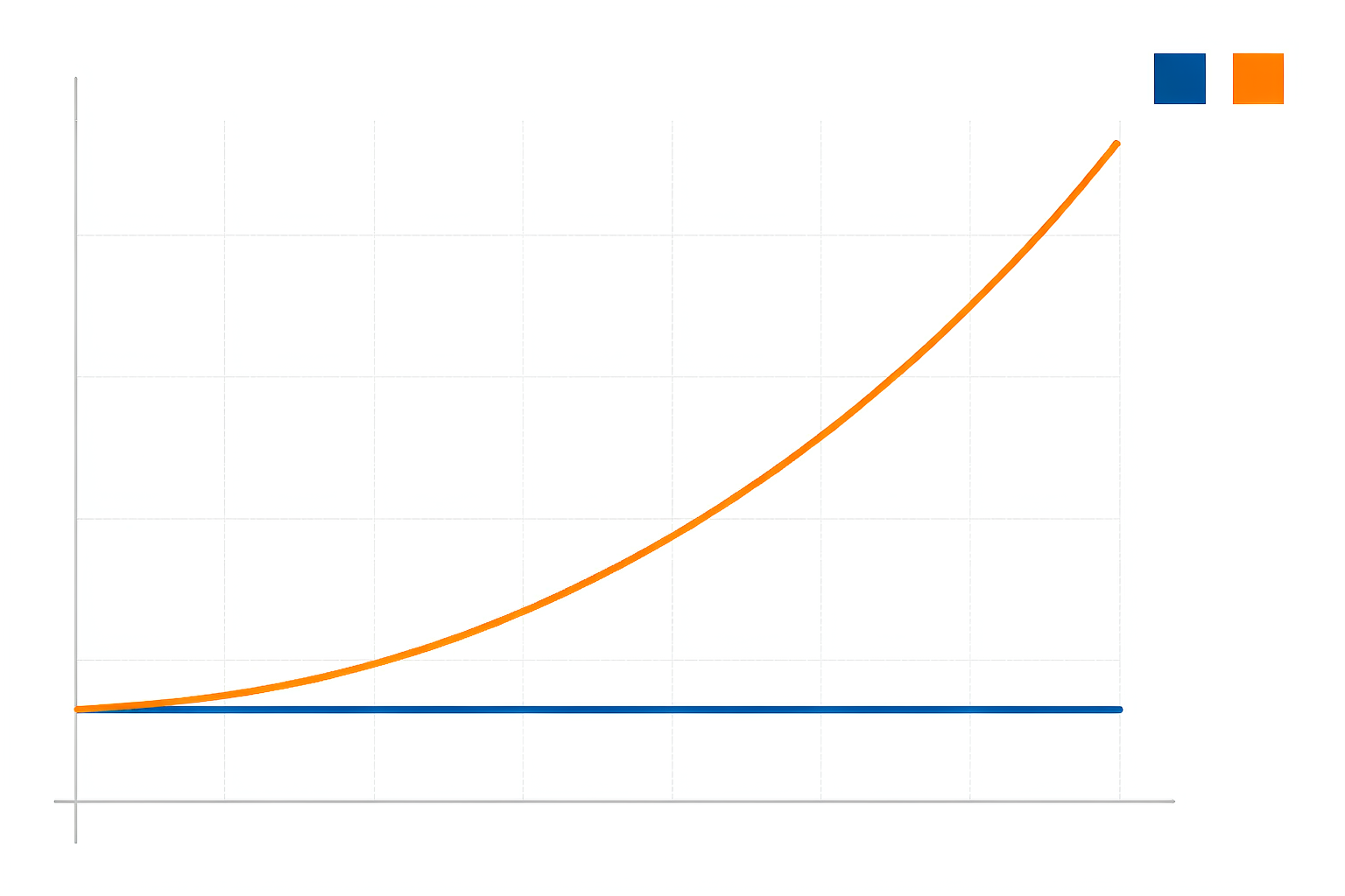
Both are stated in kilowatts on the nameplate and test report. No-load loss is constant: you pay for it every hour the transformer is energised, whether it delivers power or not. Load loss varies with the square of the load current.
Because losses end up as heat, they also drive the thermal design. Lower losses mean less heat to remove, which can allow a simpler cooling arrangement (see our power transformer cooling methods guide) and slow the ageing of the insulation system (see our oil-immersed power transformer guide).
No-load loss: the cost of being switched on
No-load loss occurs in the core, caused by two physical effects:
- Hysteresis loss, the energy needed to re-magnetise the core steel on every cycle.
- Eddy-current loss, circulating currents induced within the core laminations.
It does not depend on the load at all. The moment the transformer is energised at rated voltage, no-load loss begins, and it runs 8,760 hours a year until the unit is de-energised.
Four factors set its size:
| Factor | Effect on no-load loss |
|---|---|
| Core steel grade | Higher-grade grain-oriented silicon steel (or amorphous metal) cuts loss substantially |
| Rated flux density | Designing to a lower flux density reduces loss but needs more core steel |
| Core construction | Step-lap joints and careful clamping reduce joint and building-factor losses |
| Frequency | Loss rises with frequency; fixed at 50 Hz or 60 Hz by the network |
As a rough scale, a modern 20 MVA 110 kV unit might have a no-load loss of about 12 to 25 kW. That sounds small until it is multiplied by 8,760 hours. At 18 kW of continuous no-load loss, the unit draws roughly 158,000 kWh a year before a single amp of load is served.
Load loss: what you pay when you deliver power
Load loss has three parts:
- I²R loss in the windings, the classic resistive loss, proportional to resistance and to current squared.
- Eddy loss in the windings, caused by leakage flux, controlled by conductor transposition and stranding.
- Stray loss, induced in the tank walls, core clamps and other structural parts by leakage flux.
Load loss follows a square law: at 50% load current the I²R component is roughly 25% of its full-load value, and at 80% load about 64%. How much load loss you actually pay depends on your load profile, not only on the rated figure.
Load loss is measured by a short-circuit test at rated current and then corrected to a reference temperature (75 °C for oil-immersed transformers per IEC 60076-1), because winding resistance changes with temperature and so does the measured loss.
Stray loss deserves particular attention on larger units. If it is not controlled, it concentrates in localised spots and can create hot spots that age the insulation and the oil faster than the average temperature rise suggests.
No-load loss vs load loss, side by side
| Aspect | No-load loss | Load loss |
|---|---|---|
| Alternative names | Iron loss, core loss | Copper loss, winding loss |
| Present when | Whenever energised, even at zero load | Only when carrying load current |
| Depends on | Core steel, flux density, voltage, frequency | Load current, winding resistance, temperature |
| Scales with | Constant | Square of load current |
| Where dissipated | Magnetic core | Windings, plus stray loss in tank and structure |
| Measured by | Open-circuit test | Short-circuit test |
| Typical 20 MVA, 110 kV | About 12 to 25 kW | About 90 to 130 kW at full load |
| Reduced by | Better core steel, lower flux density, step-lap core | Larger conductor section, lower current density, conductor transposition |
How losses are measured and guaranteed
Under IEC 60076-1, losses are determined by two routine tests:
- Open-circuit test, with rated voltage applied to one winding and the other left open. It measures no-load loss and no-load current.
- Short-circuit test, with one winding shorted and current raised to the rated value. It measures load loss and impedance voltage.
Because measurements vary between units, contracts specify tolerances on guaranteed values. A widely used convention based on IEC 60076-1 is +15% on each individual loss component and +10% on total losses, though many buyers negotiate tighter figures, and penalty clauses commonly apply beyond the agreed tolerance. Confirm the figures against the edition of the standard you specify (see our power transformer testing standards guide).
Ask for the measured values from the routine test report, not only the guaranteed values. The measured figures are what you will live with.
Turning losses into money: loss capitalization
Purchase price alone is a misleading comparison tool, because a cheap transformer with high losses can cost far more over its service life. The usual correction is transformer loss capitalization: each kilowatt of loss is converted into a notional capital cost and added to the bid price.
Evaluated cost = Purchase price
               + A × (no-load loss in kW)
+ B × (load loss in kW)- A is the capitalization rate for no-load loss, in currency per kW.
- B is the capitalization rate for load loss, in currency per kW.
A is always considerably higher than B, because no-load loss runs all 8,760 hours of the year, while load loss only accumulates in proportion to the load factor and loss factor of the specific installation.
Illustrative ranges used in utility tenders might place A at roughly US$2,000 to 8,000 per kW and B at US$500 to 2,500 per kW, but these vary enormously with local energy prices, discount rate, expected load factor and asset life. Use your own figures, and give them to bidders so they optimise the design you actually want.
A worked example
Two bids for the same 20 MVA, 110/33 kV transformer, evaluated with A = US$4,000/kW and B = US$1,200/kW:
| Bid X | Bid Y | |
|---|---|---|
| Purchase price | US$420,000 | US$452,000 |
| No-load loss | 22 kW | 12 kW |
| Load loss | 115 kW | 98 kW |
| Capitalized no-load loss | US$88,000 | US$48,000 |
| Capitalized load loss | US$138,000 | US$117,600 |
| Evaluated total | US$646,000 | US$617,600 |
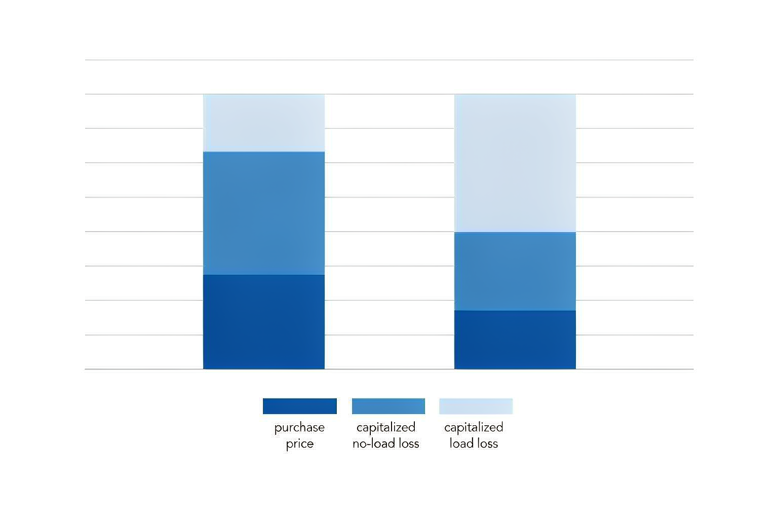
Bid Y carries a purchase price US$32,000 higher, yet its evaluated cost is US$28,400 lower. On price alone, X wins. On total cost of ownership, Y wins, and the gap compounds every year of a 25 to 40 year service life.
Real evaluations add discounting and a loss factor, but the conclusion holds: once losses are capitalized, the lower sticker price is frequently not the cheaper transformer.
How to specify low-loss transformers in your RFQ
- State loss limits as numbers, not as “compliant with IEC 60076.” Give maximum no-load and load loss in kW.
- Publish your capitalization rates A and B so suppliers optimise in the direction you value.
- Name the standard and the reference temperature (for example IEC 60076-1, 75 °C for oil-immersed).
- Require guaranteed values with defined tolerances, penalty terms, and the routine test report with measured losses before shipment.
- For no-load loss, consider specifying a minimum core steel grade or a maximum flux density.
- For load loss, consider specifying a minimum conductor cross-section or a maximum current density.
- Do not chase lower losses at the expense of integrity: cutting core or conductor size can erode short-circuit withstand and thermal margin.
Where losses meet the rest of the specification
Losses interact with two other specification choices:
- Rating and sizing. An oversized transformer runs at a lower load factor, which changes which loss dominates. See how to calculate power transformer capacity.
- Substation selection. Earthing, impedance and cooling all interact with the loss figures. See how to select a power transformer for a substation.
Conclusion
No-load loss is paid for every hour the transformer exists on the network; load loss is paid for in proportion to how hard you work it. Capitalizing both into a single power transformer total cost of ownership figure is the most reliable way to avoid buying a transformer that looks cheap and turns out expensive.
Our 35 kV to 110 kV oil-immersed power transformers are designed with low-loss grain-oriented core steel and controlled stray-loss construction, and every unit is routine-tested with measured loss figures reported before shipment.
Send us your rating, voltage ratio, cooling requirement and, if you have them, your loss capitalization values A and B. We will return a proposal with guaranteed and typical loss figures for your evaluation.